


https://robotics.sciencemag.org/content/4/35/eaav4282
Despite remarkable progress in artificial intelligence, autonomous humanoid robots are still far from matching human-level manipulation and locomotion proficiency in real applications. Proficient robots would be ideal first responders to dangerous scenarios such as natural or man-made disasters. When handling these situations, robots must be capable of navigating highly unstructured terrain and dexterously interacting with objects designed for human workers. To create humanoid machines with human-level motor skills, in this work, we use whole-body teleoperation to leverage human control intelligence to command the locomotion of a bipedal robot. The challenge of this strategy lies in properly mapping human body motion to the machine while simultaneously informing the operator how closely the robot is reproducing the movement. Therefore, we propose a solution for this bilateral feedback policy to control a bipedal robot to take steps, jump, and walk in synchrony with a human operator. Such dynamic synchronization was achieved by (i) scaling the core components of human locomotion data to robot proportions in real time and (ii) applying feedback forces to the operator that are proportional to the relative velocity between human and robot. Human motion was sped up to match a faster robot, or drag was generated to synchronize the operator with a slower robot. Here, we focused on the frontal plane dynamics and stabilized the robot in the sagittal plane using an external gantry. These results represent a fundamental solution to seamlessly combine human innate motor control proficiency with the physical endurance and strength of humanoid robots.
State-of-the-art humanoid robots are still unable to match the sophistication and adaptability of human’s innate motor control intelligence. A robotic disaster responder with locomotion and manipulation capabilities similar to those of the average human would be a valuable tool for field applications. If this technology had been available back in March 2011, the catastrophic outcome of the Fukushima Daiichi power plant nuclear disaster could have been vastly mitigated. It is estimated that, if a responder had been able to endure the deadly levels of radiation and enter the facility within the first 24 hours after the cooling system malfunctioned, the first nuclear reactor could have been stabilized (1). However, at the time, no robot of any sort had the autonomy, locomotion, or manipulation capabilities to navigate the unstructured terrain and robustly interact with the environment by opening spring-loaded doors, pushing debris, operating valves, or using tools designed for human workers. Even to this date, in the era of artificial intelligence, programming an autonomous robot to achieve human-level perception and motor control in real environments is extremely challenging and has yet to be demonstrated (2).
Humanoid robots are extremely complex systems that locomote by applying intermittent forces to the environment using contact sequences that must be planned ahead of time using the perceived footholds. These interaction forces often have nontrivial unilaterality constraints (the feet cannot pull on the ground) and are subject to difficult-to-model friction and impact dynamics. In addition, dexterous manipulation requires a whole other level of contact regulation that combines visual, tactile, and proprioceptive perception with the understanding of operation of the object being handled. The controller for an autonomous robot must produce whole-body trajectories that are subject to all these challenges while regulating balance, body momentum, inter-limb coordination, actuation and joint limits, self-collision, external disturbances, and the physical task itself (3). Reliably achieving this level of control sophistication in real-world applications is still an open problem in robotics. On the other hand, humans routinely solve these challenges while continually learning to adapt to unfamiliar scenarios. We envision that this unique human skill can be transferred to a remote robot through whole-body teleoperation. By using the body movement of a human operator to control a humanoid in real time, the machine becomes an equally capable, but expendable, first responder to dangerous situations or remote locations. This solution combines human motor control intelligence with the physical robustness and power density of robots. The key challenge is effectively mapping the human body movement to the robot and intuitively informing the operator about how closely the robot is reproducing the desired motion.
Motion retargeting from humans to legged machines or animated characters has been an active topic of research for robotics, biomechanics, and computer graphics for many years. Often, during offline retargeting, the operator kinematic data, such as joint angles and center of mass (CoM) trajectory, are measured by a motion capture system (4, 5), and the dynamic data, such as ground contact forces, are estimated by a force plate. Before the target can reproduce the motion, the data are modified to respect the robot’s (or character) physical structure, dynamic characteristics, and limitations. Frequently, this process is performed by an optimizer that approximates the target’s motions to the reference data while maintaining balancing stability (6, 7) or the nuances of the movement of a character (8, 9). This procedure is time insensitive because it is done offline; thus, the complex whole-body trajectory can be extensively refined and the resulting movement reference can be greatly optimized (10). In contrast, online motion retargeting or whole-body teleoperation (11, 12) must provide a feasible reference to the robotic system in real time, making computationally intensive planners prohibitive. In most studies of whole-body teleoperation, the robot’s balancing stability is regulated using a reduced-order model, which guides the motion mapping from the human operator to the robot (13, 14). This model is much simpler than the full-body dynamics but is competent to capture the fundamental properties of the movement that is being mapped. For instance, in the work by Ishiguro et al. (13), the reference motion provided to the robot is obtained by modifying human’s reference using stability considerations from a reduced model, allowing the robot to safely walk. However, human and machine move asynchronously because the operator does not receive any kinesthetic feedback regarding the robot’s relative motion. This unilateral information flow is a common characteristic in all of these studies. The operator commands the robot to move using his/her own body but does not receive any physical information when the robot lags behind, is perturbed, or applies forces to its surroundings.
We argue, however, that when dynamically interacting with the environment, humans heavily rely on the feedback forces from their motor actions (15). They use this kinesthetic feedback to learn how to cope with the added dynamics and to create muscle memory for recurrent behaviors. For instance, when a firefighter uses his/her entire body to push a heavy door, the subsequent motion is completely different if the door turns out to be locked or if it is free to open. Following this rationale, the teleoperated robotic responder must provide the operator with physical feedback from its actions such that the operator can intuitively use innate motor intelligence to plan the movement effectively. Thus, unilateral teleoperation strategies are unlikely to be successful in unpredictable real scenarios unless the robot has a nontrivial degree of autonomy to overwrite infeasible or erroneous commands. Yet, to the best of our knowledge, in very few studies in the literature was the operator provided with kinesthetic body feedback from the machine’s motion during teleoperation. In previous studies, forces were applied to the operator’s torso as an attempt to inform about the robot’s semistatic stability condition (16). A similar strategy using vibro-tactile feedback has also been adopted (17). However, in both studies, the machine could only perform slow movements on flat ground, and it is unclear how to extend these strategies to agile locomotion, such as walking or jumping, limiting their usefulness for real applications. In contrast, dynamic teleoperation with bilateral feedback of robotic manipulators is a well-studied research topic (18, 19). But fixed-base manipulators can apply arbitrarily large forces to their surrounding without regulating balance and step placement, differently from the top-heavy and mobile humanoid robots. Thus, existing bilateral feedback strategies used for robotic arms are not directly applicable to whole-body teleoperation of legged robots.
To address these research challenges, this paper describes a teleoperation system, shown in Fig. 1, and a control strategy to dynamically synchronize the lower-body motion of a human operator and that of a bipedal robot. Through this virtual coupling, operator and robot can simultaneously take steps, jump, and walk. The core components of human locomotion are scaled to the bipedal robot using a simplified model for legged dynamics, the linear inverted pendulum (LIP). Simultaneously, the same model is used to compute feedback forces that are applied to the waist of the operator, near the CoM, to match the operator motion velocity to that of the robot. If the robot moves faster, the human-machine interface (HMI) applies a force to speed up the translation of the operator’s CoM. If the robot lags behind, the HMI simulates drag to slow down human movement. Hence, the feedback force informs the operator about how closely the robot is reproducing human motion in real time. To focus the analysis and simplify the balancing task, we stabilized the robot in the sagittal plane using an external gantry, preventing it from falling forward or backward. However, the gantry did not provide any support in the frontal plane, and we assumed that the controllers for both these planes can be decoupled.

(A) The human operator controls the small bipedal robot, Little HERMES, to take steps in place. (B) The core components of the locomotion dynamics are mapped from operator to the robot using a simplified model, the LIP. Simultaneously, a feedback force [red arrows in (B1) and (B2)] is applied to the torso of the operator, near the CoM, to synchronize the motion of operator and robot. This feedback force is proportional to the relative instantaneous velocity between the operator and robot. (C) The machine uses human reference to reproduce stepping motions in real time.
Because of the complexity of the legged systems and the intricacy of walking mechanics (nonlinear, hybrid, and underactuated dynamics), researchers often approximate particular locomotive behaviors using simplified models. These models must capture the principal components of the full system dynamics while remaining tractable. A common strategy is to use the insights obtained from the reduced models to develop intuitive heuristics that govern the high-level controller of legged robots (20). The LIP is a powerful one-dimensional (1D) model popularly used to capture the fundamental dynamics of the CoM of bipedal systems during upright balancing and walking (14). The second-order equation of motion of the LIP describes the unstable behavior of the CoM of the system with respect to its center of pressure (CoP): the point on the ground from where a single force vector originates and summarizes the net effect of all the contact forces applied to the feet (21). By regulating the contact forces between each foot and the ground, the position of the CoP is manipulated within the area that spans the supporting feet. Movie 1 illustrates this model simplification, which is also adopted in our previous work (22). The CoP position pH(t) represents the input to the LIP equation of motion that approximates the horizontal displacement xH(t) of the human CoM
(1)where x¨H(t) is the horizontal acceleration of the CoM and ωH is the constant natural frequency of the pendulum, which dictates how fast it falls. This linear equation models the upright unstable dynamics of the bipedal system, in which the CoM naturally accelerates away from the CoP. For example, concentrating the ground contact forces under the heels causes the body to lean and later fall forward. In this model, the CoM can be actively stabilized and manipulated by properly positioning the CoP.
Previous work (23–25) demonstrated that, instead of individually controlling the CoM position and velocity [xH(t) and ẋ H(t)], it is sufficient to regulate the unstable component of the LIP dynamics to balance and walk. This fundamental component associated with the unstable LIP behavior is a composite state given by the horizontal CoM position and its normalized velocity
(2)
The state ξH(t) is named the divergent component of motion (DCM) and has been extensively used for controlling the locomotion of bipedal robots. Beyond the field of robotics, biomechanics studies have also presented compelling evidence that suggests that humans regulate a linear combination of the CoM position and its velocity, similar to the DCM, to walk and react to external disturbances (26). These studies evidence the importance of the interplay between the DCM and the CoP for dynamic legged locomotion. Inspired by this observation, we assumed that the operator stably manipulates the DCM during locomotion by shifting the position of the CoP on the ground. To command the robot to simultaneously perform the same feat, we provided a motion reference to the machine by scaling the position of the human DCM and CoP. Because the human and the robot often have substantially different physical properties, we performed this transformation using similarity analysis.
Similarity analysis of dynamic systems has often been used for the comparison of animal movements across markedly different physical scales (27, 28). For instance, one can compare the locomotion performance of a cheetah with that of a cockroach by normalizing their running speeds by their respective body lengths. By this principle, systems are geometrically similar when they have the same shape, but the dimensions are scaled by some constant factor. Two motions are kinematically similar if time is scaled by a constant number and dynamically similar if all forces follow a constant ratio. Dimensional analysis of the equations that describe the mathematical models enables the comparison of systems that have different physical or temporal characteristics. To illustrate this procedure, researchers have performed dimensional analysis of the LIP to derive the equation of motion for a dimensionless model (29). With this generalization, the fundamental behavior of the LIP was analyzed independently of particular parameters, and the motions of pendula with different lengths (or inertias) were shown to be dynamically similar.
The present work leverages this idea: We aimed to make the simplified robot dynamics similar to those of the human-reduced model via teleoperation. In essence, the robot movement ideally reproduces DCM and CoP trajectories similar to those of the operator. Hence, the motion reference mapped from human to robot and the feedback force applied to the operator were designed to guarantee this dynamic similarity. When we normalized the DCM and CoP positions using constant parameters of each system, we obtained states that ideally follow identical dimensionless trajectories, independent of scale. In the present work, horizontal states, such as the DCM and CoP, were normalized using the nominal distance between the feet (dH and dR) and vertical states using the nominal CoM height (hH and hR). Subscripts “H” and “R” indicate “human” and “robot,” respectively. States with an apostrophe indicate dimensionless values [for instance, x′R(t)=xR(t)dR]. Figure 2 illustrates the condition of dynamic similarity that our teleoperation strategy aims to achieve.

In the ideal scenario, the horizontal motion of the robot DCM [ξR(t)=xR(t)+ẋ R(t)ωR] and CoP pR are dynamically similar to those of the human operator, which means that their dimensionless trajectories match [ξ′H(t)=ξ′R(t) and p′H(t)=p′R(t)]. The CoMs are not required to coincide because manipulating the DCM is sufficient to control locomotion. Time dependency of the state variables is omitted for clarity.
This work builds on promising results for upper-body teleoperation of highly dynamic physical interactions achieved by the HERMES humanoid robot (30). Here, we complement our previous work and present a fundamental solution to dynamically synchronize the locomotion of the bipedal robot to that of the human operator. To achieve this goal, we used bilateral feedback to impose the dynamic similarity between the reduced models for the robot and that of the operator. With this virtual constraint, the operator could generate, in real time, lower-body trajectories that were dynamically compatible with the robot’s geometric, inertial, and temporal properties. To experimentally demonstrate this strategy, we developed a wearable HMI, named the balance feedback interface (BFI), and a small-scale bipedal robot, named Little HERMES (31). This work focused on studying fundamental locomotive skills such as synchronous stepping, jumping, and walking via teleoperation. Instead of being preprogrammed trajectories that the robot simply replay, these coordinated dynamic motions were induced by the operator in real time through the BFI.
To evaluate our teleoperation strategy, we used Little HERMES, a small-scale machine with physical properties substantially different from those of a human adult. These include (i) smaller total mass (mR = 6 kg) and inertial distribution, (ii) shorter nominal CoM height (hR = 35 cm), and (iii) shorter nominal distance between the feet (dR = 25 cm). It is intuitive that a short pendulum has a faster oscillation period than a longer one. Analogously, a smaller-scale robot has a faster natural frequency and, consequently, a faster stepping frequency. We used bilateral teleoperation to allow a human operator to control this machine despite dissimilar physical properties. The forward path (human to robot) of the teleoperation feedback sends the human DCM and CoP normalized positions to the robot to reproduce. The robot controller commands a motion that achieves the similarity ξ′R(t)=ξ′H(t) and p′R(t)=p′H(t) simultaneously. However, the time rate of change of the DCM is bounded by the natural frequency of the system: A pendulum cannot fall faster than its natural dynamics allows. To ensure that human and robot DCMs will evolve similarly in time, the backward path (robot to human) of the bilateral teleoperation consists of a horizontal force applied to the CoM of the operator that is proportional to the dimensionless velocity error
(3)
This equation indicates that if the robot moves (falls) faster than the operator (∣ẋ ′R∣>∣ẋ ′H∣), the force feedback will push the operator to move faster. If the robot lags behind (∣ẋ ′R∣<∣ẋ ′H∣), the force feedback applied to the operator will create the effect of drag and slow down human motion. The constant gain kH maps the dimensionless velocity error to human mass and height proportions. This means that a heavier or taller operator will experience proportionally scaled feedback forces for the same relative motion error. The derivation of this expression is presented in Materials and Methods and in previous work (32). Movie 1 summarizes the bilateral teleoperation strategy.
During teleoperation, the controller of the robot commands its CoP position on the ground to match the human reference by regulating the contact forces under each foot. When both feet exert nonzero forces (double support), the CoP is located at an intermediate point between its feet, and the dimensionless CoP is within the interval −0.5<p′R<0.5. When, for instance, the CoP is shifted to the right foot, as indicated by the magenta regions in Fig. 3B, it indicates that the left foot has lost contact and exerts zero force (p′R=0.5). When the robot controller detects this condition, it commands its left foot to follow a swing trajectory similar to that of the operator’s left foot. An analogous situation occurs when the CoP is shifted to the left foot instead, in which p′R=−0.5, and represented by green regions on Fig. 3B. These support transitions are further detailed in fig. S1. Stepping in place consists of a coordinated sequence of right and left feet support and swing as depicted in Fig. 3. Figure 3A displays the time evolution of the human and robot dimensionless DCM trajectory, and Fig. 3B shows the relative CoP trajectory. In addition, the feedback force FBFI(t) produced by the BFI, and applied to the CoM of the operator, is shown in Fig. 3C. This experiment is illustrated in movie S1. The vertical swing foot trajectory of the robot and the operator for several steps is displayed in fig. S2.

Dynamic synchronization of human and robot DCM and CoP, the two fundamental components of the LIP. (A) Comparison between human and robot DCM normalized by the distance between the feet dH and dR. The high-frequency component of the robot DCM is an artifact of the foot compliance. (B) Dimensionless CoP position for the operator (blue) and the robot (red). The areas shaded in magenta indicate right foot support, as illustrated by the cartoon in the magenta box, when the relative CoP trajectory is flat at p′R=0.5. Left foot support is analogously represented by green shaded areas and the cartoon in the green box (p′R=−0.5). The cartoons also illustrate the robot swing foot trajectory δR(t) scaled from the human reference δH(t) and the feedback force FBFI(t) in red. (C) Time evolution of the feedback force FBFI(t) applied to the CoM of the operator during teleoperation.
Additional experiments are presented in the Supplementary Materials. Figure S3 depicts a trial in which the operator commands the robot to move right to left in the frontal plane without taking steps (always double support). Human and robot DCM and CoP matched closely. The synchronization effect of the feedback force FBFI(t) is revealed in fig. S4. In this case, the feedback force was initially set to zero and subsequently enabled at about 3.5 s after the start of the experiment. The feedback force stabilized the robot DCM. Last, movie S2 depicts the ability of the robot controller to regulate the contact forces with the ground. In this experiment, an autonomous controller based on the LIP regulated the position of the CoP to maintain the DCM at the midpoint between the feet in the absence of an operator.
Forward propulsion occurs when the stance foot applies a tangential contact force against the ground in the anteroposterior direction during single support. In addition, the magnitude of this force in coordination with the appropriate stride length regulates the walking speed (29). Using this heuristic, the operator can generate a reference propulsive force by, for instance, leaning against a resistive string and taking steps in place, as demonstrated in Fig. 4A. For this experiment, the external gantry stabilizes the robot yaw (craniocaudal axis) and pitch (left-right axis) rotation, as illustrated in fig. S5B. While in single support, the stance foot of the robot applies a tangential ground contact force proportional to the reference provided by the operator and given by
(4)which modulates forward walking. In addition, the horizontal step length is regulated proportionally to the walking speed: The faster the robot walks, the longer the stride is. If α is defined negative, the robot walks backward, as shown in movie S3. We envision that this strategy can be further extended to more complex behaviors such as turning and running, which is the topic of future work.

(A) Operator commands the robot to walk by stepping in place while leaning forward and applying a static force against a string. The robot produces a similar tangential force with the stance foot, propelling the machine forward. Walking speed ẏ R is controlled by the tangential ground contact force FyR in combination with the proper stride length δyR. (B) Robot jumps by modulating the magnitude of the net contact force similarly to the operator. (B1) to (B3) illustrate this procedure and are indicated by the vertical yellow, green, and magenta lines in (B4) and (B5). (B4) Dimensionless vertical component of the net contact forces from the operator and robot. (B5) Vertical displacement of the CoM estimated from leg kinematics and from the external gantry.
The CoP is defined as the point on the ground where an equivalent net force originates and summarizes the effect of all the contact forces applied to the body. As described by the LIP model, the horizontal position of the CoP is used to maintain balance and take steps. In addition to its location, the operator also modulates the magnitude of this net contact force to regulate the CoM height. This magnitude is normalized by the total body mass mH of the operator and transmitted as reference to the bipedal robot. The machine produces a net contact force with similar magnitude to that of the operator. With this control authority, the human can command the robot to produce an upward thrust large enough to leave the ground. Figure 4 (B1 to B3) shows instances of a teleoperated jump. Figure 4B4 depicts the dimensionless reference net force FzHmHg measured by the force plate and normalized by human mass. The net vertical force produced by the robot, represented by the dimensionless quantity FzRmRg, is also shown. Figure 4B5 displays the CoM height of the robot estimated from leg kinematics zlegR in cyan and measured using the external gantry zgantryR in black. When the robot is airborne, the height estimation from leg kinematics saturates at maximum leg extension. The teleoperation of consecutive jumps is shown in movie S4.
Our research focuses on creating a teleoperation system that enables a human to intuitively control the movement of a humanoid robot while receiving kinesthetic feedback related to the motion of the robot. When synchronized with the remote robot, the operator generated stepping and walking references that were dynamically feasible for the machine to reproduce. Ideally, this teleoperation strategy eliminates the necessity for task-specific and computationally hungry perception and whole-body motion planning algorithms typically used by autonomous machines (24, 33). In this work, we focused on a fundamental locomotion synchronization strategy. This teleoperation strategy is demonstrated via three representative experiments: (i) stepping in place, (ii) walking, and (iii) jumping. Stepping illustrates the control of the fundamental balancing and locomotion mechanism. It is achieved by coordinating the interplay between the DCM and the CoP trajectories, in addition to controlling the swing leg motion and the feet placement. These are essential components required for agile locomotion in unstructured terrain. Dynamic synchronization is revealed by the point-foot design of the bipedal robot: The machine is unstable in the static sense during single support. To illustrate this scenario, movie S5 demonstrates several unsuccessful early attempts to take steps. Walking extends the basic stepping-in-place behavior to demonstrate how the operator can regulate the locomotion of the robot. Similar strategies can be used to extend this capability to other locomotive actions such as running and turning. Last, jumping exemplifies the ability to generate large contact forces and to deal with impacts. We envision that the ability to aggressively push against the ground and accelerate the body upward can be extrapolated to whole-body manipulation tasks that require regulation of large contact forces such as pushing or lifting heavy objects.
We assume that the motion error evident in Fig. 3 (A and B) originates largely from (i) the mechanical properties of the foot sensor material and (ii) the point contact of the spherical foot. The foot sensor underdamps the vibrations caused by unmodeled impacts with the ground, causing the entire robot to shake momentarily and introducing noise in the velocity estimation (and consequently the DCM). This can be evidenced when comparing Fig. 3A with the first 4 s of fig. S3A, when there were no impacts, and the motion error was very small. Selecting a different material with improved damping properties for the foot sensor will likely reduce this issue. The effect of the foot compliance is also evident in the high frequency ringing in Fig. 4B4. The DCM tracking performance is further degraded during single support or at large amplitudes of the CoP trajectories, which is demonstrated by comparing the first and second halves of fig. S3. We assume that the lack of ankle supination or pronation torque prevents fine regulation of the robot CoP when standing on one of the feet. Because of this degradation in control authority, the robot motion briefly lags the operator reference. The addition of a more substantial foot and the utilization of balancing strategies that use angular momentum regulation (29) could help mitigate this problem. Last, it is difficult to define the acceptable tracking error that can be tolerated for successful synchronization largely due to the uncertainties introduced by the human. It is likely that the expertise of the operator heavily affects how limitations of the system are anticipated and compensated for.
This pilot study is based on a planar linear model with limited dynamics. In addition, the robot is not designed to balance in the sagittal plane without the gantry due to the simplicity of the leg design and the point-contact feet. Future implementation of more complex 3D motions, such as running and turning, will require more sophisticated model and machine (34) and is a topic of future work. However, the fundamental idea of dynamic similarity presented in this work should be preserved even for complex systems. Another limitation of the present study originates from the exclusively horizontal force feedback, FBFI, applied to the operator. We assume that including additional kinesthetic feedback for total angular momentum, for instance, will enable the utilization of strategies based on reactive inertia, such as the “hip strategy,” for balancing or absorbing external disturbances (35, 36).
In addition, an evident drawback of our method relates to a notorious issue of telerobotics: communication delay. This issue becomes even more pertinent for time-sensitive occasions, such as during highly dynamic motions. Although not within the scope of the present study, it is still unclear how much delay the strategy proposed in this paper can tolerate. However, given the relatively slow natural frequency of the legged systems in this work, we expect that the bilateral teleoperation will still be successful for moderate amounts of communication lag. In addition, we argue that the challenge of achieving high-speed remote communication stands in a considerably shorter technological horizon than achieving reliable human-level perception and motor control for autonomous robots. Thus, we believe that bilateral feedback teleoperation stands as a promising shorter-term solution for deploying robots to real applications.
The goal of our strategy is to transfer the burden of perception of the surroundings and the motion planning to the human, considerably reducing the autonomy requirements for the robot. We assume that, with sufficient training, the operator will learn how to naturally cope with the robot-added dynamics. Using the kinesthetic feedback, the experienced operator should develop the “muscle memory” to effectively control the machine. This adaptation to dynamic conditions has been demonstrated for simple dynamic systems (37). We assume that this operator will be able to adapt to unfamiliar scenarios and improvise motions that the machine has not performed beforehand—a fundamental human skill and a capability still far from being achieved by autonomous machines. Future work includes an evaluation of the learning rate for inexperienced operators and the definition of training procedures to improve the synergy between human and robot. We would like to explore how human intention can be anticipated using other biosignals, such as gaze tracking, electromyography, and electroencephalography. Last, on the human side, we will look into the trade-offs between the required feedback (kinesthetic, visual, auditory, etc.) to the operator and their associated cognitive load, especially for long periods of operation.
We envision that a robotic disaster response robot will seamlessly combine the power density of machines with the control skills of humans to perform highly demanding physical tasks. Toward this vision, the control architecture presented in this work introduces fundamental ingredients to dynamically couple the operator to the humanoid robot. Our future research will focus on combining the manipulation performance demonstrated by HERMES (38) with the locomotion control introduced here by Little HERMES. For instance, a disaster responder would use these combined abilities by taking steps to build up momentum and to subsequently dump that energy to break down a blocked door, as shown in Fig. 5. Future work will address several core challenges to create a capable humanoid disaster responder. These challenges include the development of a generalized teleoperation strategy for 3D motion in parallel with a legged robot capable of balancing itself without the gantry. At that point, we must prescribe the boundaries of human-robot shared autonomy, which is defining the extent to which the robot follows human motion or makes autonomous decisions to modify suboptimal, conflicting, or erroneous commands that may jeopardize stability or the completion of the task at hand.

We intend to combine previous results for manipulation, enabled by HERMES, and locomotion, introduced here by Little HERMES, to develop a capable robotic responder. This robot will leverage human motor control and perception skills to perform physically demanding tasks that require whole-body coordination in addition to balance regulation.
Last, the method presented here could also be further explored under the lights of motor rehabilitation. For such application, we envision that the physiotherapist could provide intuitive physical cues and support for gait rehabilitation through the BFI by “teleoperating” a patient connected to a second BFI. Both individuals would become more synchronized as the patient walking performance improves with treatment. In addition, the kinesthetic feedback to the physiotherapist could potentially provide valuable information about the impairment condition of a particular patient.
The proposed teleoperation system requires three major components: (i) the bipedal robot, (ii) the BFI and operator, and (iii) the bilateral feedback teleoperation law. First, we describe the bipedal robot developed by our group, highlighting design features that enable proper force control and agility for legged locomotion. Next, we describe the design of the BFI for high-speed motion capture and kinesthetic body feedback. Last, we derive the bilateral feedback law that maps the information between the operator and the remote robot. We briefly describe the controller of the robot here, and the reader can find further information in our previous work (31, 32). The experiments presented here were conducted with a single experienced operator. The data for the experiments were collected after the operator became familiar with the system; at that point, each experiment was conducted a single time. Emergency stops were included to shut off the BFI or the robot in case of failure or danger.
The experiments presented in this paper were conducted with Little HERMES (31), shown in Fig. 6, a small-scale bipedal robot with three degree-of-freedom (DoF) legs and point feet. During the stepping in place and jumping experiments, a boom with a spherical base joint constrained the robot to move in its frontal plane. For the constrained walking experiment, a passive linkage structure stabilized the robot yaw and pitch rotation but allowed the robot to translate in the anteroposterior direction. Both gantries are shown in fig. S5.

The design of the small-scale robot is based on principles specific for agile legged locomotion. (A) Custom actuators were designed for impact mitigation and high-bandwidth torque control. (B) Lightweight limbs have negligible inertia and allow fast leg swing. A timing belt transmits the torque to the knee joint from the motor mounted coaxial to the hip axis. (C) Impact-robust and lightweight foot sensors measure three-axis contact forces and were used as contact switches. (D) A ruggedized IMU estimates the robot’s torso posture, angular rate, and linear acceleration at 250 Hz. (E) Real-time computer sbRIO 9606 from National Instruments controls the robot at 600 Hz. (F) The robot is powered by two three-cell lithium-polymer batteries in series. (G) A rigid and lightweight frame minimizes the robot mass.
Little HERMES uses a number of design principles that allow contact force regulation at high bandwidth. Each leg has three DoFs: hip ab/adduction, hip flexion/extension, and knee flexion/extension. The actuators were designed from off-the-shelf gimbal motors with a custom single-stage 6:1 planetary gearbox and an integrated current-control driver with energy regeneration (39). An efficient 1.6:1 timing belt transmission connects the knee joint to its actuator, mounted proximal to the body and coaxial with the hip flexion/extension actuator. These features were combined with the lightweight leg design (together about 10% body mass) to minimize energy losses from frictional and inertial forces. These features enabled high-bandwidth force control from motor current and leg kinematics alone, without requiring springs or force/torque sensors (31, 40).
Custom foot sensors monitored the contact forces with the ground. We used these sensors to estimate the robot CoP and as contact switches but not for closed-loop contact force control. As shown in fig. S6, these lightweight devices (about 50 g each) can measure three-axis forces and are composed of an array of four piezoresistive sensors that are loaded by the deformation of a urethane hemisphere during interaction with the ground (41). These impact-robust and lightweight sensors are more appropriate for legged locomotion than conventional stiff, heavy, and bulky load cells or force/torque sensors. In addition, the polymeric deformable material could be designed to have stiffness and damping properties tuned to the application. We found the material used for our sensors to be excessively springy and intend to replace it with polymers with improved dampening characteristics, such as sorbothane. Figure S7 illustrates the open-loop contact force control performed by the bipedal robot.
The embedded real-time computer, an sbRIO 9606 from National Instruments, runs the robot control loop at 600 Hz. It communicates with the actuators via a dual-channel high-speed CAN bus card NI9853 and with the feet sensors with an analog input card NI9205. The IMU, VectorNav VN-100, provides body orientation and angular rates at 250 Hz. Two three-cell lithium-polymer Venom batteries in series power the entire robot.
Human motion data were collected by the BFI, a highly backdrivable HMI designed to be transparent to the user and shown in Fig. 7. This high-speed motion capture system used 12-bit encoders to measure human torso position and orientation in space (five DoFs, no torso yaw). The three-DoF spatial position of the feet was estimated using two passive arms connected to the operator’s feet. The BFI can apply large horizontal feedback forces (up to 100 N) to the operator’s waist, near the CoM. The feedback force and torso posture tracking were performed by two actuation modules, each with three DoFs (one actuated and two passive), as depicted in Fig. 7A. The torso posture was estimated by solving the forward kinematic of both modules together. The desired feedback force FBFI was achieved by coordinating the force produced by the both actuation modules. Figure S8 shows the force control performance for one of the stepping-in-place teleoperation experiments. A six-axis force plate captures the human CoP and the normal and tangent components of the ground contact forces that the operator applies during motion. The real-time computer, a cRIO9082 from National Instruments, ran the control loop and estimated human posture at 1 kHz. The communication rate with the robot was also performed at 1 kHz.

(A) Custom HMI was designed to be transparent to the operator and to capture human motion data at high speed (1 kHz). (B) BFI has two underactuated modules that together track the position and orientation of the torso and apply forces to the operator’s CoM. (C) Each actuation module has three DoFs, one of which is a push/pull rod actuated by a DC brushless motor (Maxon EC90 Flat). A pair of load cells measures the actual forces applied to the operator. These sensors were not used for closed-loop force control. Force control was achieved via current-based torque control of the motors. (D) A series of linkages with passive joints were connected to the operator’s feet and track their spatial translation. (E) Real-time controller cRIO 9082 from National Instruments closed the BFI control loop and sampled data at 1 kHz. (F) A 3 feet–by–3 feet force plate estimated the operator’s CoP position and measured the shear and normal components of the operator’s net contact force.
During teleoperation, the robot reproduces human motion by tracking reference DCM and CoP trajectories. To achieve this, the controller of the robot computes two components of the net horizontal force applied by both legs together to the CoM: (i) FrefxR(t) is a feedforward term calculated by scaling the human ground contact force and (ii) FerrorxR(t) is responsible for stabilizing the motion and compensating for tracking errors from the desired DCM reference. The linear compensation uses a constant gain Kx. With these two components, the horizontal equation of motion for the CoM of the robot is given by
(5)or
(6)
The net horizontal force applied to the CoM of the operator has two terms: (i) FxH(t) is the horizontal component of the contact force that the operator generates against the force plate and (ii) FBFI(t) is the feedback force applied by the BFI. The horizontal equation of motion for the human CoM is given by
(7)
To derive the expressions for the feedforward term FrefxR(t) and the feedback force FBFI(t), we use the desired CoP similarity
(8)and the CoP Eq. 1 to obtain
(9)
If we assume that the robot reproduces human DCM reference (ξ(t)dR=ξH(t)dH or FerrorxR=0), we use Eqs. 6 and 7 to write
(10)
The expressions for the feedforward term and the feedback force are computed by satisfying the equality (Eq. 10). The law that scales the operator contact force to provide a feedforward term for the robot controller is given by
(11)
The force feedback that is applied to the operator is defined by
(12)
From the desired net contact force to be applied to the CoM, the robot controller computes the individual force contribution for each foot. In this work, this force distribution problem is performed by solving a linear system (31). For more complex robots, this problem is commonly addressed by an optimization-based solver, often formulated as a quadratic program (3, 25). A detailed analysis of this bilateral feedback law was done in our previous work (32).
The high-level control loop of the system is depicted in Fig. 8. First, human motion information is transformed into reference for the robot using a reduced model, the LIP. Next, the robot controller uses this reference to compute the desired ground contact forces for the right and left feet. The “tracking correction” block describes the stabilizing equation for FerrorxR(t). Last, the BFI applies a feedback force to the operator that is proportional to the dimensionless relative velocity of human and robot CoM, according to Eq. 12.

Human kinematic and dynamic data on the far left were transformed into a reference for the robot using the reduced model, the LIP. This transformation computed the desired DCM state ξ′H and the appropriate contact forces FrefxR and FrefzR that the robot must apply to the ground to reproduce human motion. With this information, the robot-embedded controller computed the required contact force to be applied by each foot. The feedback FBFI applied to the operator is proportional to the relative motion velocity between operator and robot.
When one of the robot feet loses contact with the ground, it follows the trajectory of the swing foot of the operator. The desired Cartesian deviation δR(t) from the nominal stance is computed by scaling the operator foot deviation δH(t) from nominal stance. During right leg stance, for instance, the desired left foot swing trajectory follows the deviation from nominal stance given by
(13)
robotics.sciencemag.org/cgi/content/full/4/35/eaav4282/DC1
Fig. S1. Stances during teleoperation.
Fig. S2. Swing foot vertical trajectory.
Fig. S3. Right-to-left motion teleoperation via bilateral feedback.
Fig. S4. Motion synchronization using force feedback.
Fig. S5. Gantries used to constrain the robot during experiments.
Fig. S6. Soft force sensors used for the robot feet.
Fig. S7. Bipedal robot contact force control.
Fig. S8. BFI force control.
Movie S1. Teleoperation of stepping in place.
Movie S2. Robot autonomous balancing controller.
Movie S3. Teleoperation of constrained walking.
Movie S4. Teleoperation of consecutive jumps.
Movie S5. Compilation of unsuccessful stepping experiments.
This is an article distributed under the terms of the Science Journals Default License.
ROS
Turtlebot Learning Tutorials:
See the simulated turtlebot in Gazebo.
Cruise around in the Gazebo world and use RViz to "see" what's in it.
Use the navigation stack to create a map of the Gazebo world and start navigation based on it. This tutorial shows you how to use its SLAM (gmapping) package to build a map, and then autonomously navigate from point A to point B
Theory and Algorithm:
ROS Cheat Sheet:
http://www.tedusar.eu/files/summerschool2013/ROScheatsheet.pdf
Mlody1111,lody1111

Walking upside-down requires a careful balance of adhesion and weight, and specialized trekking tools to combat the constant tug of gravity.
Each fly foot has two fat footpads that give the insect plenty of surface area with which to cling. The adhesive pads on the feet, called pulvilli, come equipped with tiny hairs that have spatula-like tips. These hairs are called setae.
Scientists once thought that the curved shape of the hairs suggested that flies used them to grip onto the ceiling. In fact, the hairs produce a glue-like substance made of sugars and oils.
Sticky proof
A research team from the German Max Planck Institute for Metals Research recently studied more than 300 species of wall-climbing insects and watched them all leave behind sticky footprints.
|
||
| Mystery Monday | ||
| Each Monday, this LiveScience series explores an amazing aspect of the world around you. Previous articles: |
"There are over one million insect species," team leader Stanislav Gorb told LiveScience. "We suppose that all of them have the secretion, but it is difficult to be 100 percent sure."
Gorb presented the findings at the Annual Meeting of the Society for Experimental Biology in April.
Flies need sticky feet to walk on ceilings, but not so sticky that they get stuck upside down. So each foot comes with a pair of claws that help hoist the gooey foot off the wall.
Flies use several different techniques to get unstuck: pushing, twisting, and peeling its footpads free.
"Methods involving peeling are always the best, because they require less energy to break the contact," Gorb said.
The combination of the feet hairs' rounded tips, the oily fluid, and a four-feet-on-the-floor rule help the inverted insect take steps in the right direction.
Lessons for robofly
Following in the fly's footsteps, robots are on their way to climbing walls.
Gorb's research team worked with a robotics group from Case Western Reserve University to design robotic feet that mimic a fly's footing.
On the bottom of the feet of a 3-ounce robot that's all legs, scientists tacked on a sticky, furry manmade material that resembles the hairy surface of a fly foot. The researchers also taught the robot how to gently peel its foot off a glass wall, just like a demure insect.
"It's the first time a robot has climbed glass in a way that was inspired by an animal," said mechanical engineer Roger Quinn.
iSprawl is the youngest and fastest sibling of Autonomous version of Sprawl robot family. I joined BDML at the end of this Office of Naval Research project and designed iSprawl for the first creation at Stanford.
Sprawl robots are designed by inspiration based on study of cockroaches. - Watch iSprawl's running on ground. Other movie clips are on video page
Whereas other sprawl robots utilize pneumatic system, iSprawl is equipped with battery and electric motor and power transmission system that convert rotary motion to reciprocal leg thrust. What most makes iSprawl unique is push-pull cable transmission system. Since Sprawl family turn its orientation by rotation of their leg with respect to hip joint, power transmission path is not fixed. Which is frequent problem in legged robot with centered engine.

Usage of steel cable as pulling transmission is very common
as you can find very easily in bicycle brake and car throttle. iSprawl's cables, however, thrust and pull the legs in high speed
(up to 17Hz) without significant energy loss. This enables
iSprawl's light and fast movement of legs leading to fast
locomotion up to 15 body-lengths/sec(2.3m/s).
Critical function prototype of push-pull cable system.
see BDML iSprawl twiki page to learn more about iSprawl.
Predecessor of iSprawl, the first sprawl robot that operates with autonomous power. It uses hydraulic power transmission system. The idea was to explore hydaulic power transmission to distribute power to the legs. The tubes contain water and the system works like hydraulic brakes on a car, with a single master piston and slave pistons at each leg. Aqua Sprawl is assembled in a bathtub to prevent air bubbles.
After many design iterations, including remachining the original Sprawlita pistons to put in double seals to handle negative pressure on the return stroke, a version of Aqua Sprawl was produced that ran fairly well:
A movie of Aqua-Sprawl
Although Aqua Sprawl ran reasonably well, there is a fundamental limitation to the achievable speed because while retracting the pistons, only atmospheric pressure is available. On the other hand, this could be a good design for underwater use!
CASE WESTERN RESERVE UNIVERSITY
Take a look at some of our best videos!
Tumbleweed
Mini Whegs™
MMALVs
Unmanned Ground Vehicles
Whegs™ II

| Swarm Robotics | the Neuroscience and Robotics Laboratory We're developing a framework for self-organizing robot systems based on decentralized estimation and control. The goal is to "compile" desired group behaviors into local communication, estimation, and control laws running on individual robots. For properly designed control laws, the interactions of individual robots result in the desired group behavior, without any centralized control. | |
| Source: nxr.northwestern.edu/research/swarm-robotics | |


#!/bin/bash

NEW_VERSION=30

REMOTE_HOST=hs-242-lejos.internal

ID_FILE="${HOME}/.ssh/lejos_rsa"

STDERR_REDIR="${HOME}/.nxj/install.log" # "/dev/null"

function install-files {
    mkdir -p ~/.nxj
    curl -o ~/.nxj/classes.jar http://$REMOTE_HOST/classes.jar 2>$STDERR_REDIR
    cp ~/.nxj/classes.jar ~/Applications/lejos_nxj_classes.jar
    curl -o ~/.nxj/upload.sh http://$REMOTE_HOST/upload_script.sh 2>$STDERR_REDIR
    mkdir -p ~/.ssh
    curl -o $ID_FILE http://$REMOTE_HOST/lejos_rsa 2>$STDERR_REDIR
    chmod 0600 $ID_FILE
    chmod a+x ~/.nxj/upload.sh
    mkdir -p ~/Library/Preferences/org.bluej/extensions
    curl -o ~/Library/Preferences/org.bluej/extensions/bluejos.jar http://$REMOTE_HOST/bluejos.jar 2>$STDERR_REDIR
    curl -o ~/.nxj/bash_commands http://$REMOTE_HOST/nxj_commands.sh 2>$STDERR_REDIR
    echo "Latest LeJOS client successfully installed! Please restart terminal now."
    echo "(Or run 'source ~/.nxj/bash_commands' in your current terminal sessions.)"
}

cd ~

if [ "x$LEJOS_VERSION" == x ]; then
    echo "Installing LeJOS client..."

    mkdir -p ~/.ssh
    echo -e "\n\nHost lejos\n    HostName $REMOTE_HOST\n    User lejos\n    IdentityFile $ID_FILE">> ~/.ssh/config
    echo -e "hs-242-lejos.internal,10.30.0.242 ssh-rsa AAAAB3NzaC1yc2EAAAADAQABAAABAQDv7aJaWOLa5HDekddGlymnF50zWg4oUVHFfbuihk1hP0bwQLpqXCwIEK3eloL5rwhkacncR/+22W5zPChWuNBp14Dipgcon9yuJp2ypqO5t+jRda1Lo19E6nAty3/FVpyGi/ZWGO7JdiB/ZFmr6MPUZ6bN3nTgCE2GH82Ezjhxb4QN4LS44C1+OEQ/b/TFuKUaIwEqKnzU0/sq1c8RFfYR9ztb10DRpFgMU83UJO3uZUTdkzQVzPVjuuLXXcXTR+4u9g9l7fKVs+3BABTtQFTl3EtrULqAzSCJfLsFxQ6B9CA77gC5uXzlwxQvKNpiNm5kRtRpM86awpGGMO1M/JjF" >> ~/.ssh/known_hosts

    #echo -e "$ID_FILE" | ssh-keygen 2>$STDERR_REDIR >/dev/null

    #echo
    #echo "Enter \"yes\", then \"lejos\" at the following password prompt."
    #echo

    #{ cat ${ID_FILE}.pub; } | ssh lejos@$REMOTE_HOST "umask 077; test -d .ssh || mkdir .ssh ; cat >> .ssh/authorized_keys; test -x /sbin/restorecon && /sbin/restorecon .ssh .ssh/authorized_keys"

    install-files

    ssh lejos "mkdir -p ~/$USER" -o StrictHostKeyChecking=no 2>/dev/null
    echo

    echo -e "\n\nsource ~/.nxj/bash_commands" >> .bash_profile

elif [[ $LEJOS_VERSION -lt $NEW_VERSION ]]; then
    echo "Upgrading LeJOS client..."

    install-files
else
    echo "LeJOS client already setup and up-to-date."
    echo
    echo "If things aren't working, please reset your SSH and Bash configurations and then try again."
fi


http://hs-242-lejos.internal/
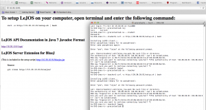
To setup LeJOS on your computer, open terminal and enter the following command:
curl -s http://hs-242-lejos.internal/setup.sh | bash
LeJOS API Documentation in Java 7 Javadoc Format
http://hs-242-lejos.internal/api/
LeJOS Server Extension for BlueJ
(This is included in the setup script) http://hs-242-lejos.internal/bluejos.jar
Source:
git clone http://hs-242-lejos.internal/bluejos/
*********** Previous **********
Terminal:
hs-242-imac-t:~ userblah$ curl -s http://10.30.10.94/setup.sh | bash
smb://lejos@10.30.10.94
This installs the lejos files
create a java file in a folder: Lejos, get to it and
Lejos ReadOutLoud eText teachers1415
Lessons Rosters workspace
hs-242-imac-t:Documents userblah$ cd lejos
hs-242-imac-t:lejos userblah$ ls
MotorTutor1.class MotorTutor1.java
hs-242-imac-t:lejos userblah$ nxjc MotorTutor1.java
hs-242-imac-t:lejos userblah$ nxjlink MotorTutor1
MotorTutor1.class 100% 703 0.7KB/s 00:00
bring brick to pc, connect, search, and upload MotorTutor1


![]()
![]()

![]()


Must login with gmail.

Re-start the application: ctrl - alt -esc


